
Just enough kernel to get by (part 1) : Interrupts handling
This is the first article of a serie about Windows kernel architecture. Goal is to give a basic ovebitrview of the kernel space, just enough to be able to start developing a simple driver and debug it. It does not intend to replace the lecture of Windows Internals and will not replace an advanced course on the subject.
For the sake of simplicity i will stick to the 32 bits Intel architecture and will not cover the new stuff introduced by Vista/7/8.
However the vast majority of the content should stillbit be applicable to the latest Windows versions (32 & 64 bits).
So the program is :
- A bit of hardware
- Windows kernel overview
- Big picture
- Kernel objects
- Object manager
- I/O manager
- Memory Manager
- Windbg
- Overview
- Essentials commands & extensions
- Scripting
- kernel debugging
- WDM (Windows Driver Model)
- Overview
- Driver object
- Device object
- DevNode
- IRPs
- User mode / kernel mode communication
- Writing a simple driver
- Introduction to WDK
- Build environment
- the Hello World driver
- Handling IOCTLs
- some fun stuff :)
- About filter drivers …
###A bit of hardware Intel 32 architecture defines 4 level of privileges, known as Rings.
On most OSes only the ring 0 and 3 are used.
-
Ring 0 (Kernel mode) gives access to all CPU instructions & complete memory space (including I/O space)
-
Ring 3 (User mode) has a limited instruction set, no direct hardware access, and memory access is limited to the process boundaries
Ring level has nothing to do with scheduling, each thread will live 2 lifes, one in User mode and one in kernel, with a dedicated stack for each mode.
The only exceptions are the system threads, some special kernel mode only threads with no user mode part ( the “Zero” thread is one example, this thread is dedicated to overwrite freed memory pages with “0” when the system is idle, yep that a dull life…)
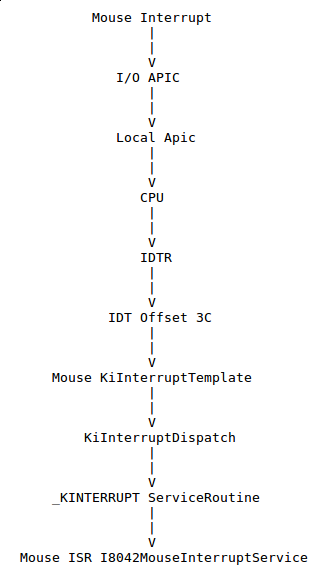
Another hardware important element is the interrupt mechanism.
Interrupts can be seen as hardware events used to signal the processor that something requires its immediate attention.
- Devices interrupts
Devices (network card, keyboard, etc..) will raise an interrupt to signal the processor that they have new information to handle (an incoming network packet, a key press, …).
- Trap / exceptions
This basically occurs when the processor faces an error, like a divide by zero, a memory fault etc…
- Software interrupts
Those are interrupts generated by sofware, for example INT 2E is used to transition from user mode to kernel mode, INT 3 is used to generate a sofware breakpoint etc …
The number following the INT instruction is called the interrupt vector, this is basically an index in the IDT (Interrupt Descriptor Table or Interrupt Dispatch Table). The IDT will associate an interrupt vector with a specific function which will service the given interrupt. In the WDK world such a function is called an ISR (Interrupt Service Routine).
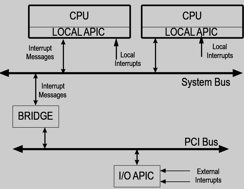
From an hardware point of view, interrupts are handled by specific piece of hardware called a PIC (Programmable Interrupt Controller). Nowdays we usually have the new version of the PIC called an APIC (Advanced Programmable Interrupt Controller) builtin directly in the processor die.
Benefits of the APIC are :
- Multiprocessor aware
- More interrupt lines (256 vs 15 for the PIC)
There is one APIC per CPU ,and each APIC can communicate with the others APICs using an IPI (Inter-processor interrupt message).
One big part of the interrupt handling job done by the APIC is to manage interrupts priorities, each interrupt line is given a priority and the APIC will ensure that no incoming interrupt with a priority lower or equal to the current serviced interrupt will reach the processor, this is often refered as Interrupt Masking.
Note that some special interrupt cannot be masked and will always reach the processor no matter what , they are called NMI (Non-maskable interrupt) and they are usually meant for non-recoverable hardware failure, meaning that you have a serious hardware issue…
Interrupts coming from devices are first handled by the I/O APIC, a specific chip built in the chipset, its role is to distribute the interrupts to the local APICs of each CPU, thus enabling SMP support.
When an interrupt reaches the CPU , the processor and the OS interrupt routine will save the registers state in the kernel stack in order to be able to resume previous execution flow. This set of registers saved state plus some additional information (for example error code) is usually called a Trap Frame, we will cover it later when playing with windbg and the .trap command.
Let’s get a bit deeper in the interrupt dispatch mechanism, first how does the processor knows where the IDT is located ? Answer lies in the IDTR register, this is a 48-bit register divided in 2 parts, a 16-bit IDT limit and a 32-bit base address.
The IDT has a maximum of 256 entries, each entry is 8 bytes long and contains things like flags, segment selector, gate type (see the Intel documentation for more details), and the offset or address of the ISR.
The offset it splitted in 2 parts , bits 0..15 for low end bits and bits 48..63 for high end bits.
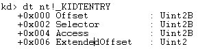
The Windows type describing an IDT entry is _KIDTENTRY
The simplest way to display the IDT in windbg is to use !idt command
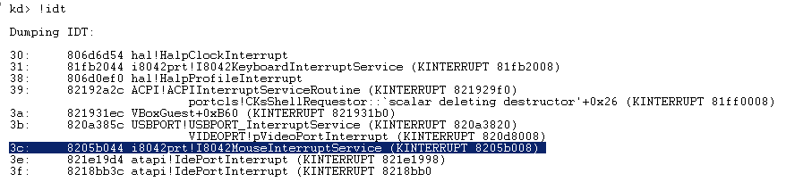
So for example, if we want to take a closer look at the mouse ISR i8042prt!I8042MouseInterruptService :
Using the !idt command is handy but this command plays its litlle magic and hides the internal plumbing, so let’s do the job ourself.
The IDT address is located in the IDTR register and each entry is 8 bytes, so if we want to dump the entry 3C (our mouse ISR) we do :
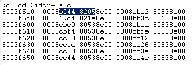
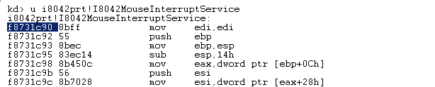
So our ISR address is 8205b044, but …. wait, we just dumped I8042MouseInterruptService and its address was f8731c90, what’s going on ??!!
Well, before calling the drivers ISRs the system needs to perform some tasks, like masking the lower priorities interrupts in the APIC, raising the IRQL (Interrupt Request Level , will detail this soon), etc…
So rather than filling the IDT with the ISRs, the system fills it with some “glue” code or to be more precise “template functions”.
Each template is taken (copied) from the KiInterruptTemplate function and dynamically modified to match the according ISR.
Let’s take at our mouse “template” function found in the IDT :
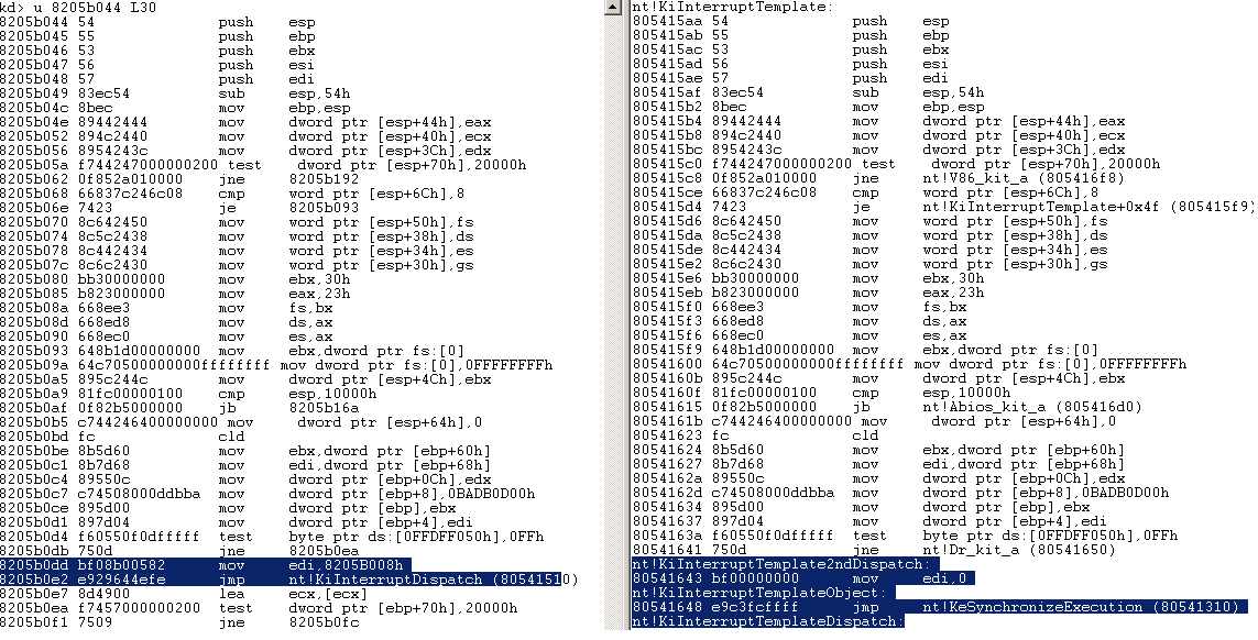
We can see that most of the code is a perfect copycat of the original KiInterruptTemplate function. However one interesting difference is that the mouse “template” calls the KiInterruptDispatch function and puts in EDI the address 8205B008h.
This address points to an interrupt object of type _KINTERRUPT :
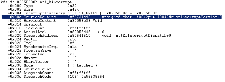
As you can see above, the interrupt object references the mouse ISR in its ServiceRoutine field.
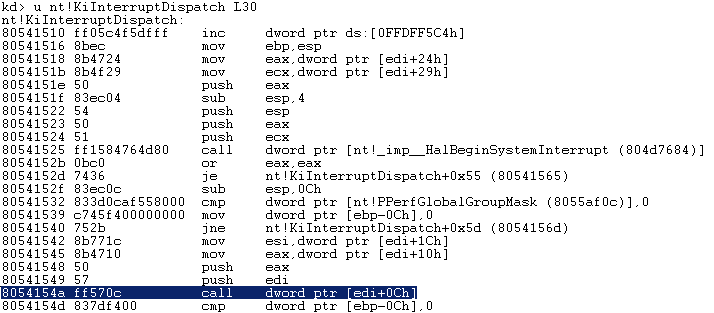
If we now look at the KiInterruptDispatch code we can see that it is calling the interrupt object ServiceRoutine :
So short version is :
How is the interrupt object created ?
It’s the role of the driver to fill up the structure by calling IoConnectInterrupt.
That’s all for this first post, hope it was not too boring, live long and prosper!